Pokewalker · Hardware
The infrared had to go
The Pokéwalker that came with HeartGold and SoulSilver talked to a DS over infrared, and the DS is where the Pokémon were. A Game Boy has no infrared at all — it has six pins on the side and a cable. So the rebuild starts by deleting the transceiver and putting a link interface in the hole it leaves, and the interesting part is how little silicon that takes.
A Game Boy link is six pins and almost no parts
The IrDA sheet is gone — the Vishay TFBS4711 and everything hanging off it. What replaced it is a 74LVC2G17 dual Schmitt buffer and five resistors.
Two of the six EXT pins are driven by the console at 5 V TTL, and those go through the buffer to get down to 3.3 V. Its inputs are 5 V tolerant at a 3.3 V supply, so there is no divider and no bidirectional shifter. The leg going the other way needs nothing at all: TTL's input threshold is 2.0 V, so the device's 3.3 V output drives the console directly.
The device is the clock slave. A Game Boy link has no chip select, which is why this is a job for the RP2350's PIO rather than its PL022 — the hardware SPI's slave mode wants a select line to stay byte-aligned, and there isn't one.
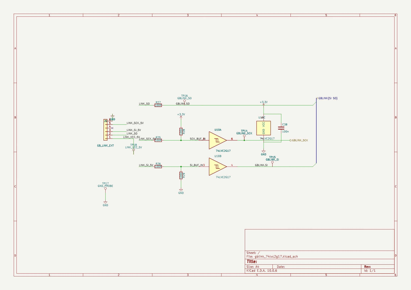
Nothing in it is Gen-1 specific. The sheet carries SPI Mode 3 bytes and encodes no byte counts, so a Gen 2 trade is a firmware problem, not a board respin.
The connector is a row of pads, because nothing else fits
J5 is a new footprint rather than a part off a shelf: a 1×6 row of 1.27 mm solder pads. The
largest free rectangle on the back copper near the MCU measures 6.25 × 6.25 mm, and the
smallest 6-way JST SH needs 9.8 × 5.2 mm. The only place a real connector fits is the far end
of the board, beside the USB-C and the power management.
Pads keep every connector option open, and they are what bring-up on a breadboard wants anyway. Five test points sit on SCK, SI, SO, ground and the link's own 5 V — this interface has never seen a console, so it is instrumented rather than trusted.
The placement came from a measured free-space map of the back copper, not from eyeballing it. That board outline is a rounded Pokéwalker shape with three screw-hole cutouts in it, two of them sitting right inside the band where the parts had to go, and KiCad's own board-polygon call does not treat a cutout as off-board. A search that does not exclude them will happily put a footprint in a hole.
The Poké Ball look is paint, and it has to be
The shell is two machined halves split at the ball's own band, with the belt clip cut into the back — the arrangement of the real device, whose clip lives on a swappable back cover.

That picture cost an afternoon of looking for a camera angle before the geometry settled it. A Poké Ball icon is a sphere seen level with its own equator. This part is a ⌀70 mm disc 19 mm thick, so the same level camera renders a 69.5 × 19 mm lens. There is no elevation that turns a disc into a ball, and the only view whose silhouette is a true circle is straight at the face — where the real band is edge-on at the rim and invisible.
So the stripe across the face is paint. The band round the equator is real: a 3.9 mm sunken recess with a chamfered shoulder each side and the parting line down the centre of it, 0.6 mm deep at its deepest out of a 1.2 mm wall. Red above and white below is a render choice; no finish decision has been made.
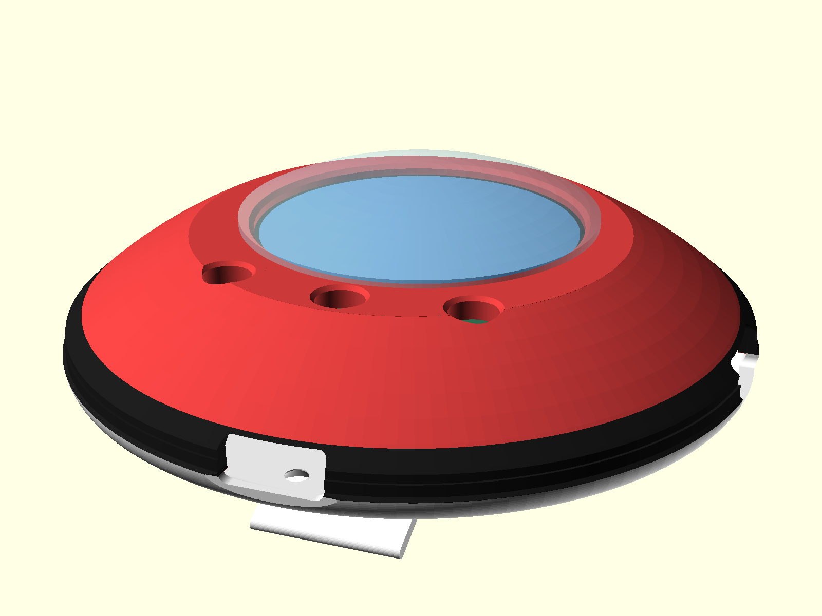
It is not a half-and-half ball and it cannot be while it is a Pokéwalker. Red covers about three-quarters of the object's height because that is the real device's proportion. Making it read 50/50 is a form-factor decision, not a paint one.
Boring the screen pocket flattens the dome
The bezel has to be constant thickness over the window, so the outer surface is machined flat out to the bezel radius — on ⌀70, a flat 44 mm across, sitting 5.02 mm below where the sphere would have been. A fifth of the front is a disc. That is exactly why it looks faceted next to a real Pokéwalker.
The real device does not solve this in the housing either. It puts a clear cover over the front and lets that carry the curve the screen cannot. So does this one.
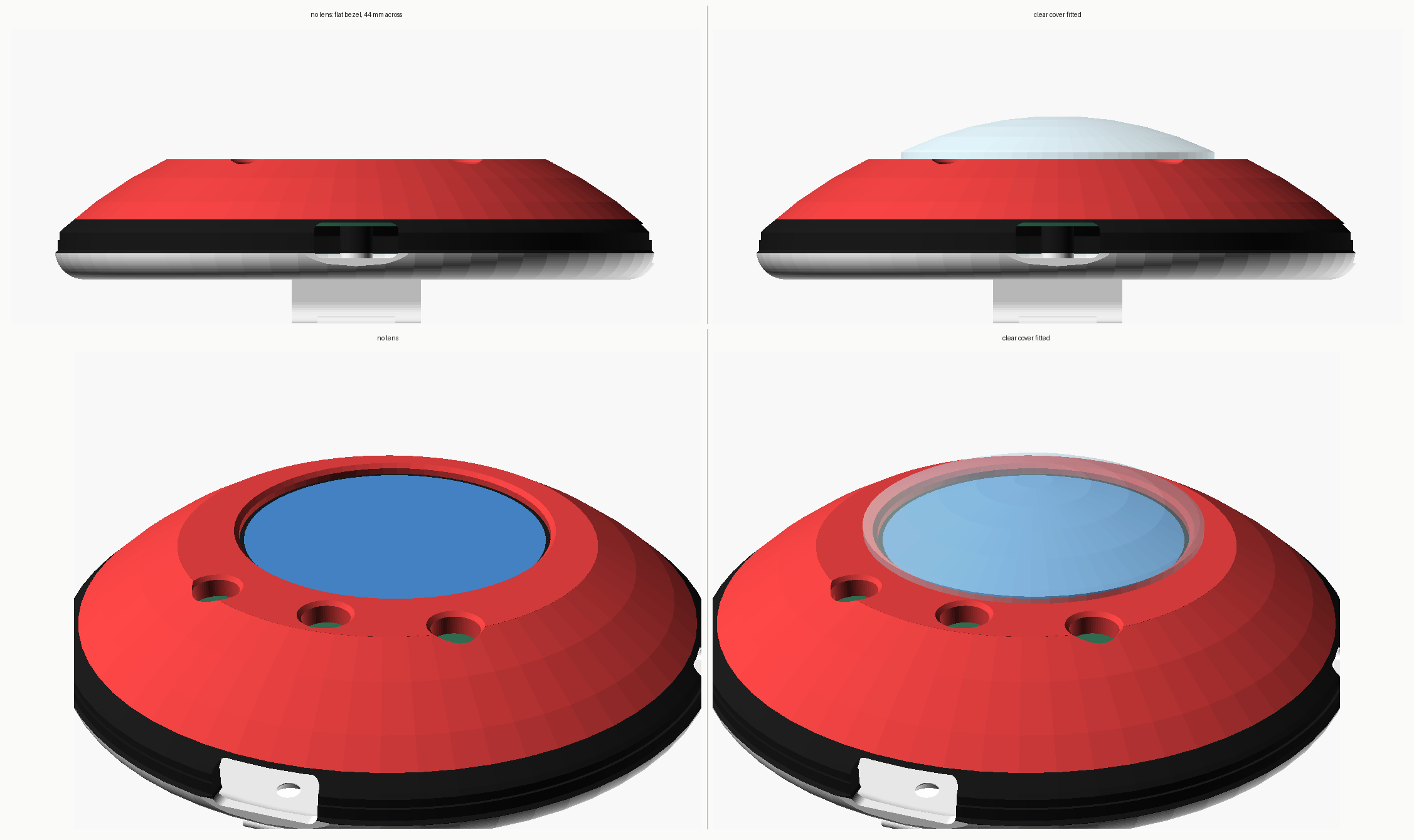
It is the tightest thing in the model. Measured from the screen centre, the window's chamfered mouth ends at r=17.2 mm and the nearest button's mouth begins at r=18.47 mm. Everything the cover needs on the face — flange, land, slip fit — lives in that 1.27 mm.
The check for it is an intersection rather than an assertion: the target builds the shared volume of cover and shell and fails unless it comes out with zero facets. Forcing the fit 0.5 mm the wrong way makes it report 1280 facets, which is how you know the check has teeth.
The plug cannot reach the socket
make check fails on the ⌀70 configuration, and it is right to.
The board's minimum enclosing circle is ⌀50.50 mm. The bore it sits in is ⌀67.6. That leaves the USB-C receptacle's mouth 7.27 mm inside the shell wall, and a USB-C plug seats its overmould against the case with about 6.5 mm of nose — all of which is needed inside the receptacle, not crossing seven millimetres of fresh air. No chamfer or funnel fixes it.
Three things do, and they are all board decisions: make the board reach the wall, move the connector out on a flex or riser, or give up on USB-C and accept a recessed pogo or magnetic charger. It is a tighter trade than it looks. In a ⌀60 shell the bore is ⌀57.6 at the split plane but the dome has already narrowed to ⌀54.9 a millimetre above it, so a board big enough to reach the wall has to sit at or below the split line — which eats the space underneath that the receptacle needs, and the back has to get deeper to pay for it.
And ⌀48, the size that gets quoted as the answer, does not satisfy it either: in a ⌀60 shell a ⌀48 board still leaves a 4.8 mm gap and the plug still cannot reach.
The clip will go slack
Report and instinct both say a printed 316L clip takes a set and stops gripping. Machining it does not help, because that is not a process problem — 316L is not a spring material in any process. As drawn, the clip grips when new and goes soft.
Three ways out, none of which change the geometry: machine the back from 17-7 PH in condition A and age-harden it afterwards, machine it in titanium TC4, or redraw the clip as a hook that barely flexes and lets geometry do the retention. The back is a separate piece held by three screws, so trying a second one in a different material is cheap.
What the numbers are
Both configurations export and both were weighed from the real solid volumes at 7.98 g/cm³, not estimated from a wall thickness: 86.1 g for ⌀70 (front 36.4, back 49.7) and 62.7 g for ⌀60. Both are a long way under the 143 g a solid ⌀70 ball suggests, because a flat-backed Pokéwalker is a long way from a sphere. The clear cover adds about 1.3 g in acrylic.
Every dimension that could plausibly change is a named parameter, and the model asserts its
own rules while it renders — that the band leaves at least 0.5 mm of wall, that the screw
heads stay on the flat, that the bosses clear the board. The board geometry is not typed in
either: the outline, the mounting holes, the buttons and every footprint's courtyard are
pulled straight out of the .kicad_pcb, so a board change and a stale shell cannot coexist
quietly.
What is not done
The link nets are placed but not routed, and hand-routing is the only option. Freerouting was tried properly on this board and is not usable: it plateaus at 62 unrouted and 417 violations, its fanout stage rewrites the whole board rather than the nets you asked for, and importing its result takes the board from 981 tracks to 203 — it wipes routing on seventy nets that were already fine. It also routes straight through the screw-hole cutouts, because the export format does not carry them as keepouts.
Beyond that: the interface has never been run against a console, the ball size is still open, and a keyed bayonet joint that makes the front half swappable — Poké Ball, Great Ball, Ultra Ball, and a Team Rocket ball that is a fan design rather than canon — is drawn and parked until the side buttons are settled, because the lugs have to miss the ports.
Every figure here is measured in the pokewalker hardware repository and re-derivable there: masses from the exported solid volumes at 7.98 g/cm³, clearances from `make check` against the real `.kicad_pcb`, net connectivity from KiCad's own netlister. The link interface has never been run against a console. The board is mamba2410's picowalker, forked; the original device is Nintendo's.
← Back to devlog